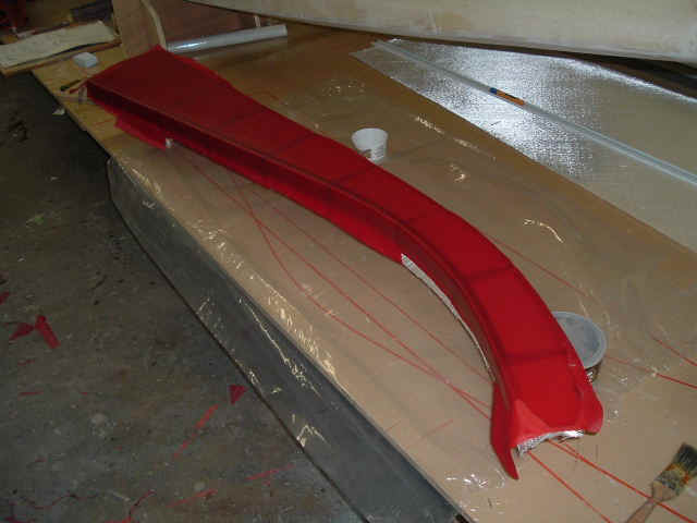
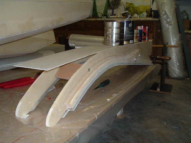
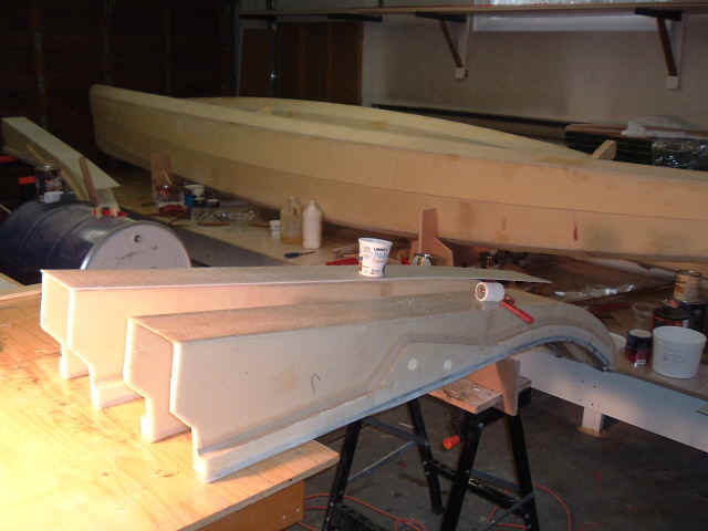
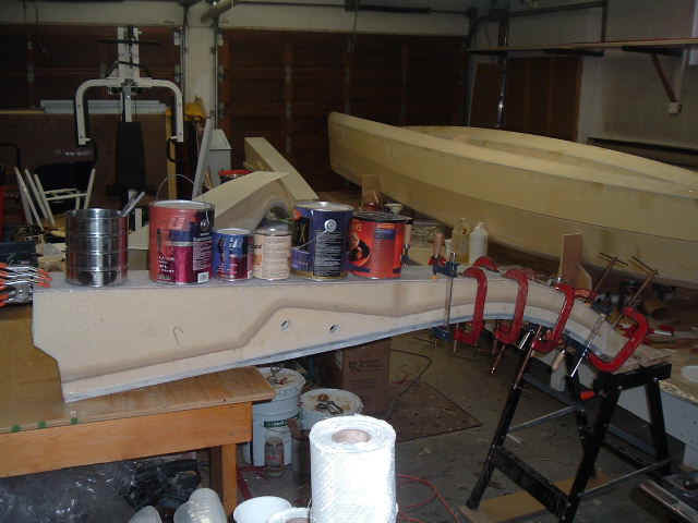
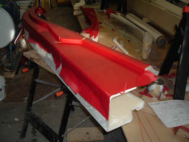
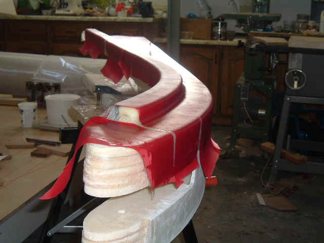
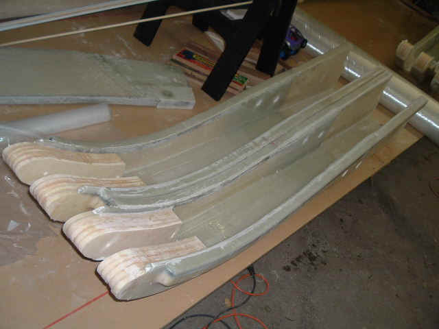
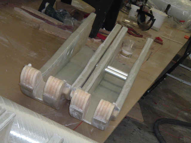
Finally my 4 cross-beams are complete and ready to attach to the floats after 85 hours of work.
I experienced "trojan horses" and "e-mail worms" if you know what I mean... But now my PC is feeling better.
I tougth initially that the beams would be simple to build...NOT.
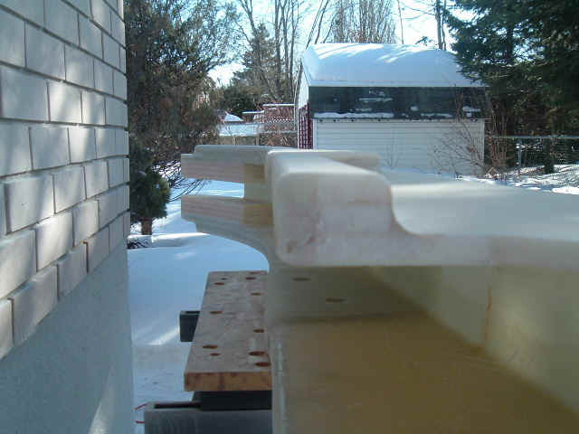
They were so much trouble to make, to obtain a barely curved shape in the end... A lot of work for nothing in my opinion. Aluminum profiles would be superior and probably lighter. If we could stamp those in sheet metal it would be perfect!
Each beam weighs 38 lbs.
Lots and lots of grinding and sanding to do between the numerous laminating jobs. I think the method used for the Scarab650, with a female mold, is far superior and I still wonder why Ray changed it for the Scarab22 (Fouilles-moé...).
From now on, hit me on the head if I ever say again "this should be quick to make"...!
I will add some comments with the photos at a later time...
I am not following Ray's laminating schedule. I figured there were too many little fiberglass pieces.
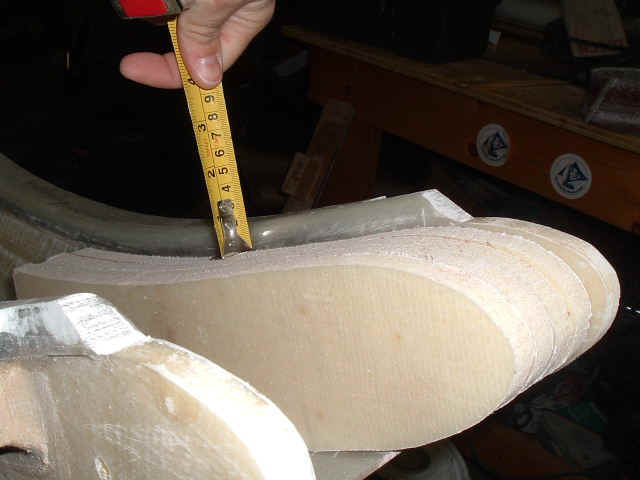
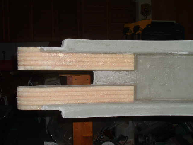
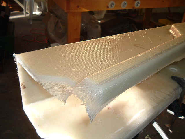
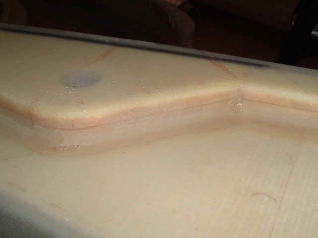
It is very important to create LARGE radius on all corners that are to be laminated over. The plans don't specify a value but at least 10mm radius in necessary for 600 gsm double-bias glass. If too sharp, the glass will lift away from the surface creating ugly air bubbles that need to be repaired.
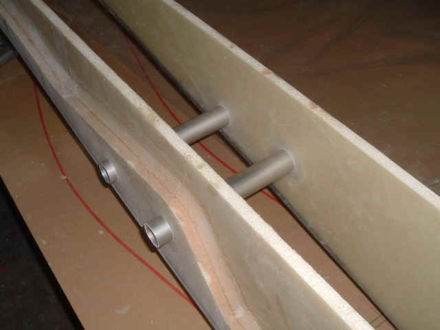
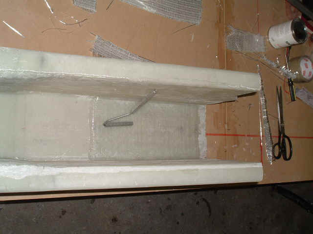
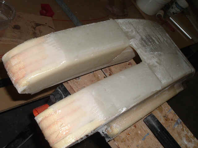
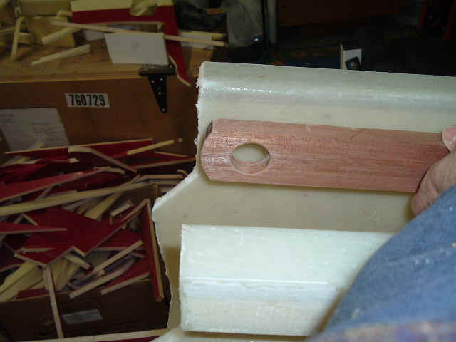
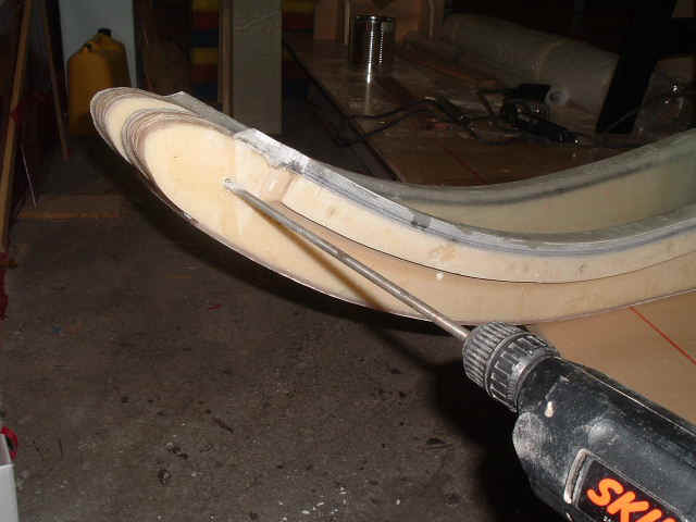
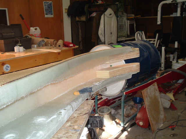
Using dummy tubes to align beam halves.
This part was laminated and cut as specified in the plans... 3 inches too long!
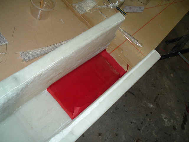
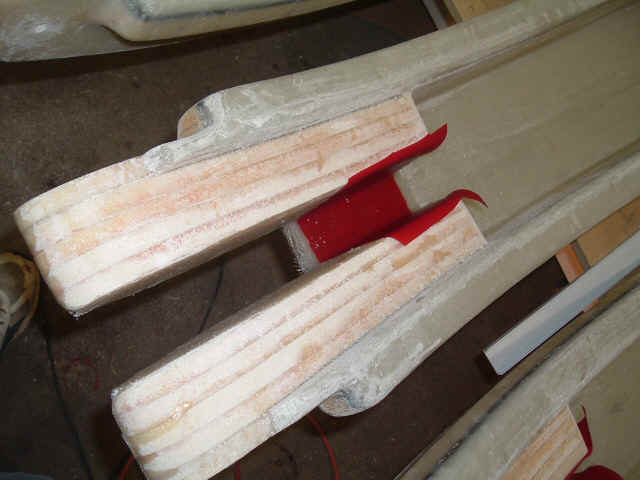
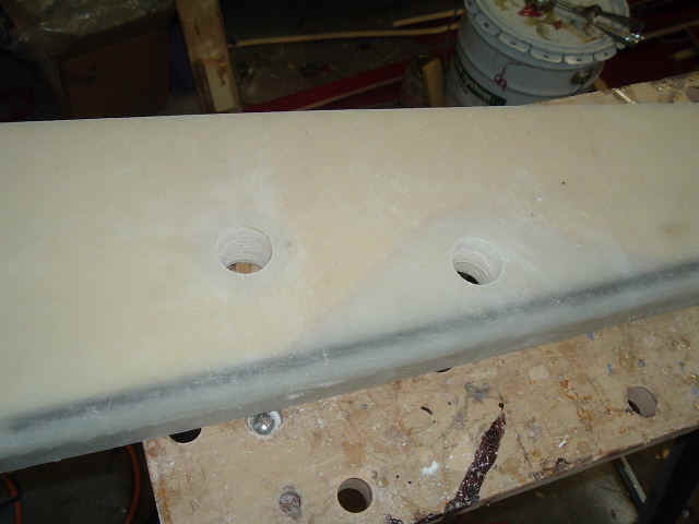
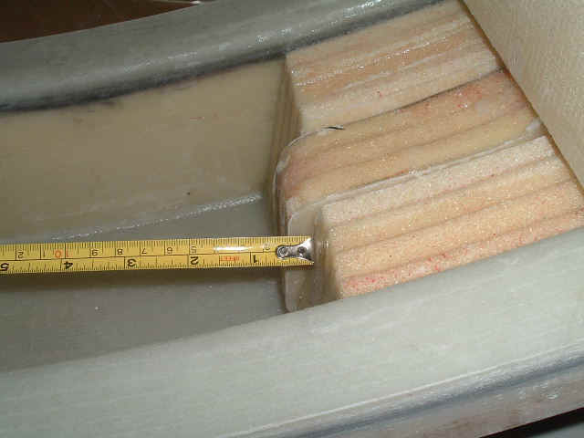
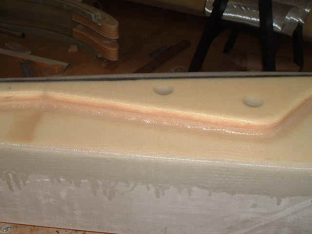
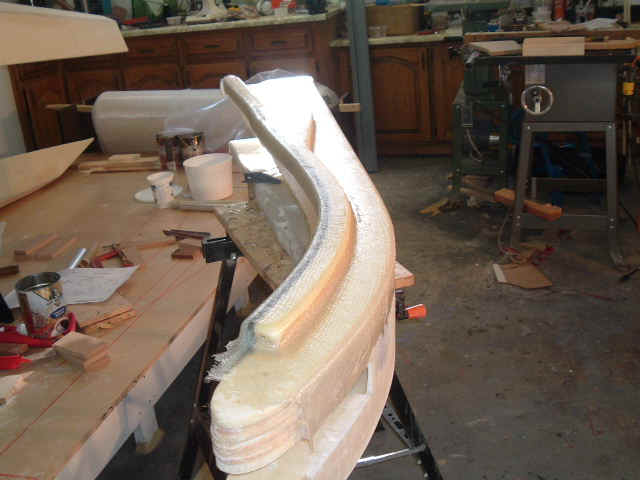
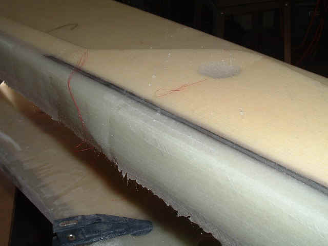
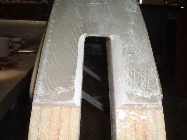
The foam filler pieces are too low by about 12 mm. Too late to fix... I will just glass over this when I attach the beams to the floats.
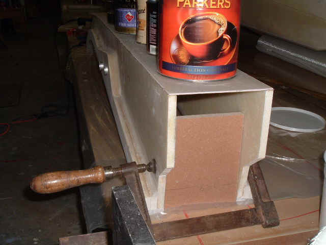
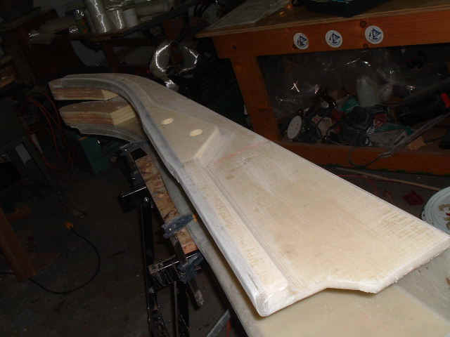
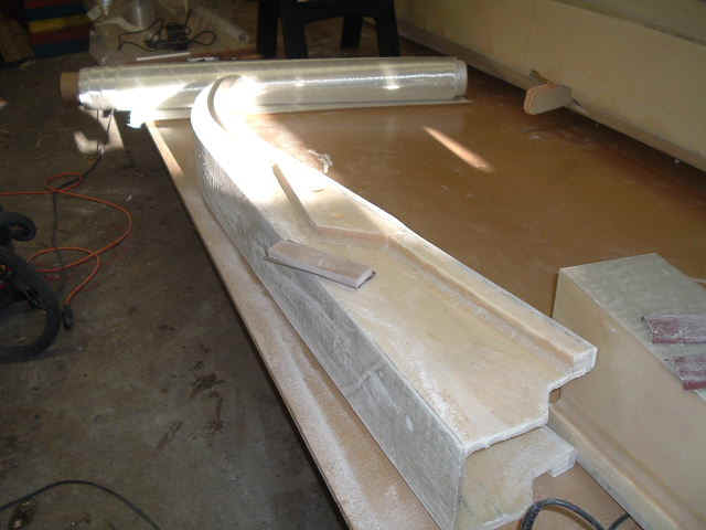
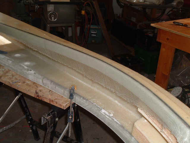
Checking the fit of the first layer of top cap laminate. 2 layers are required. Note the paint cans I use as weights.
A lot of trouble for a square fiberglass box...
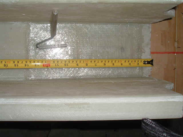
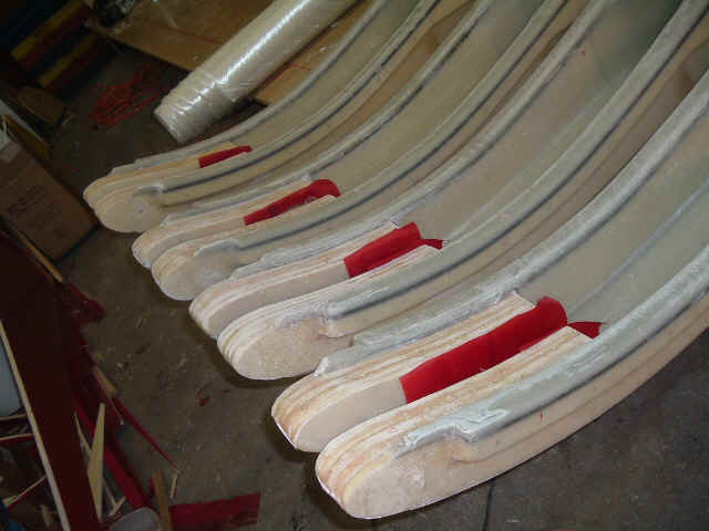
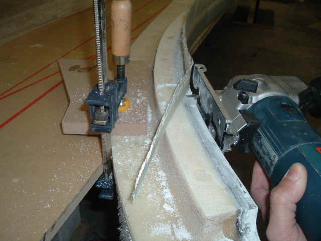
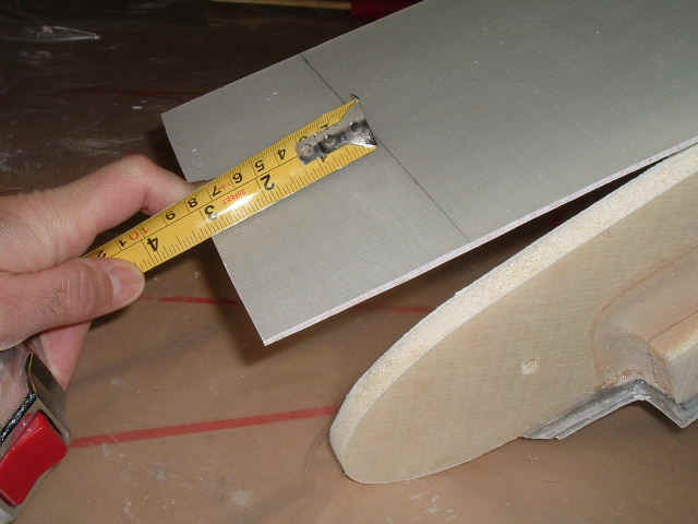
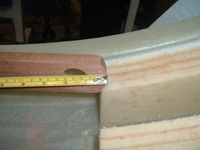
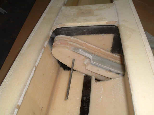
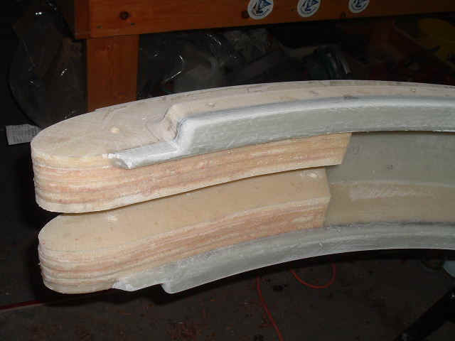
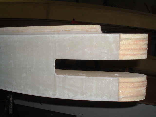
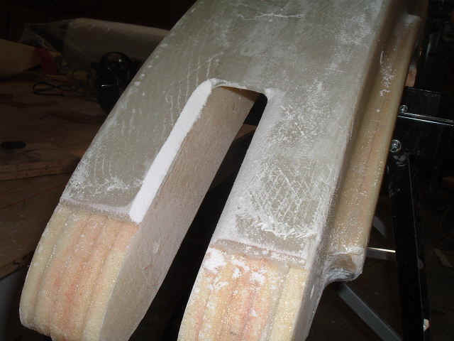
Checking the fit of the lower folding struts. I verified this by making wooden dummy struts. That was a wise thing to do because I discovered that the boat would be impossible to fold completely due to oversize foam pieces at the end of the beams. They are too long by about 10 mm and interfere with the folding strut end.
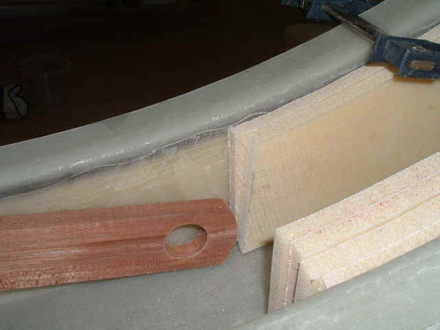
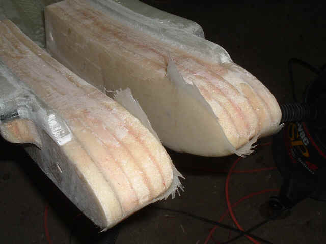
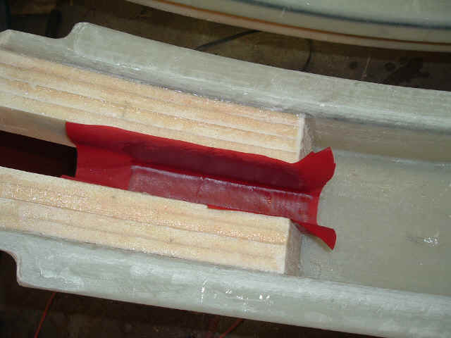
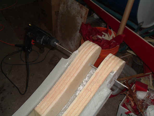
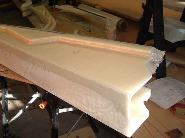
Foam pieces re-shaped correctly. This would be a hell of a job to do on finished beams, with the glass and everything.
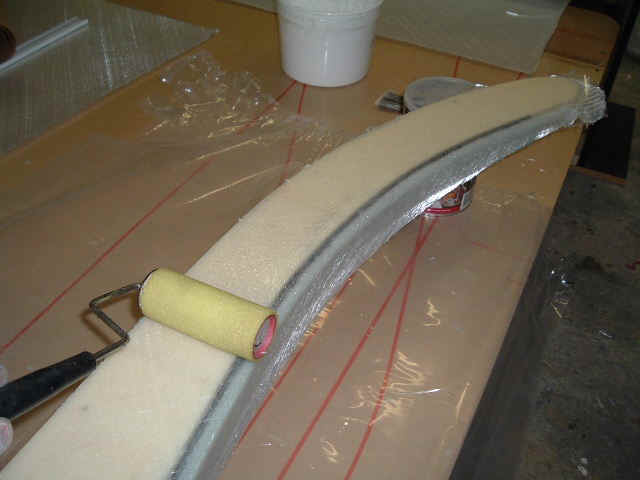
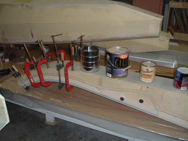
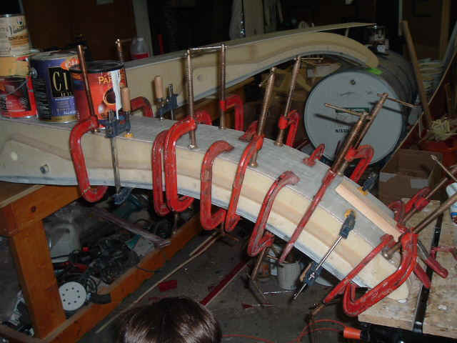
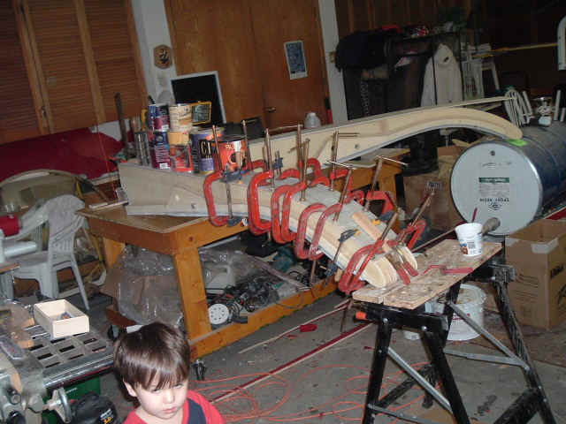
Gluing on second layer of top laminate.
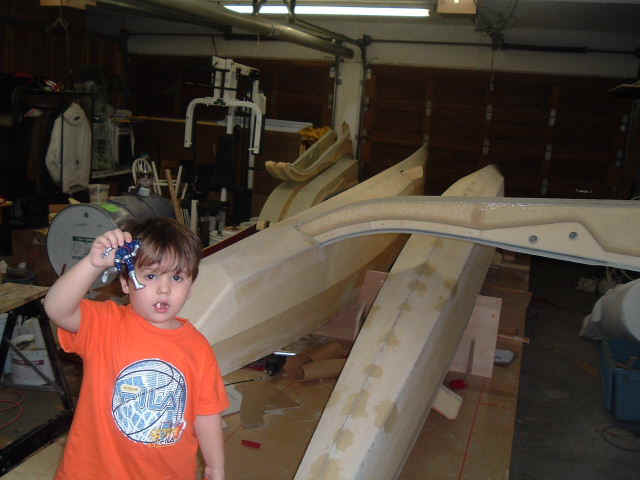
Checking the fit of a beam in a float. Looks good but the hole cut in the float is HUGE.
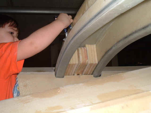
Is that enough foam for you? At least it is good flotation... My little kid is having as much fun as me!
Float bulkhead stub too long. Not a big deal, I will cut this flush before attaching the beam to the floats.
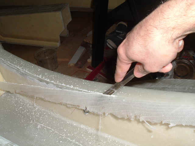
Rounding edges. Make LARGE radiuses!!! 10mm minimum. It is interesting to try to make nice round edges on foam panels. The glass face is super hard and the foam is super soft.
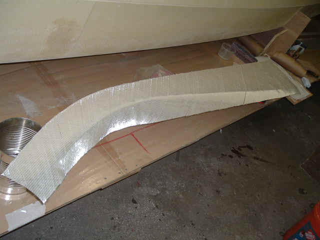
Glassing the beam sides in one piece.
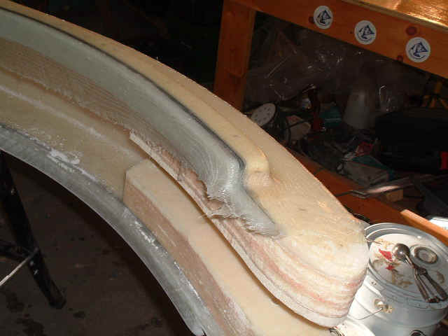
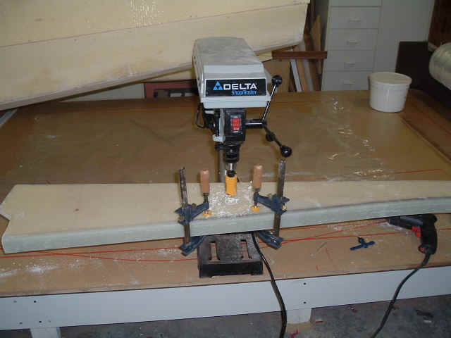
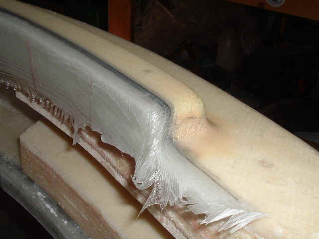
Air bubbles under the glass. This is what happens if the edges are too sharp. To repair, I drilled 3 holes in each bubble, 1/8" dia.: one in the center and 2 at the ends. I then used a small syringe filled with epoxy putty and filled the bubbles from the center holes. Worked great.
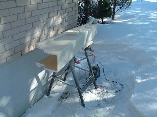
I did some edge grinding outside. Very dusty job... I noticed that fiberglass dust looks just like snow!

No comments...
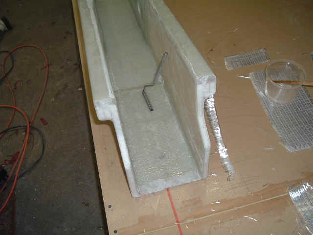
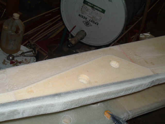
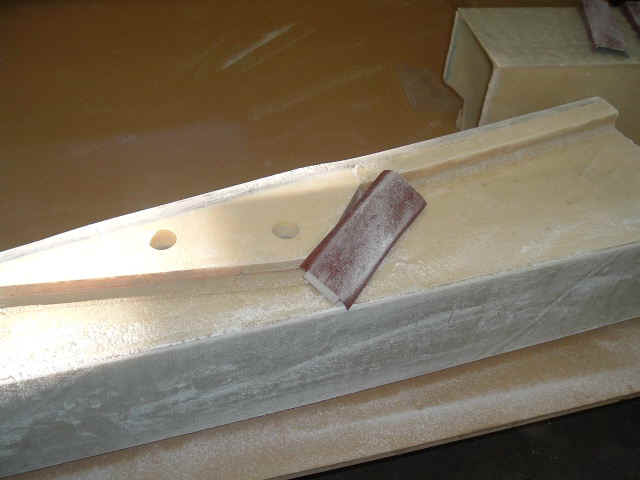
This is a patch of glass I added to reinforce the inboard end of the beams. Nothing is specified in the plans but My Finite Element Analysis shows high loads there.