glue back together. A lot of fitting also. Most templates are not really to
net shape and some sanding / cutting is required to assemble everything.
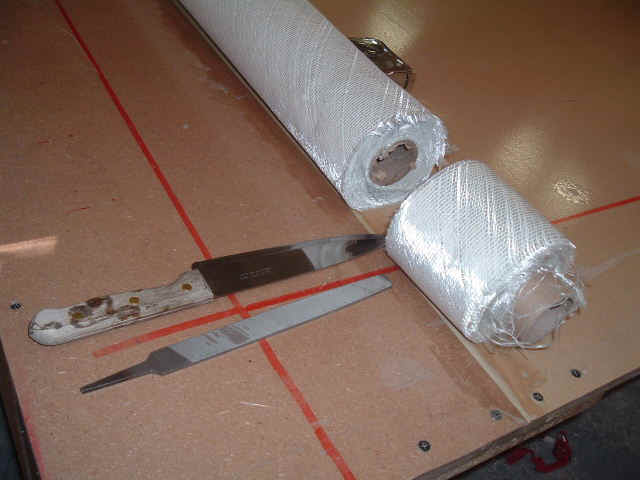
Many short lengths of glass tape, more than 160 pieces of 3' long glass
tapes for the inside of the floats alone!!!
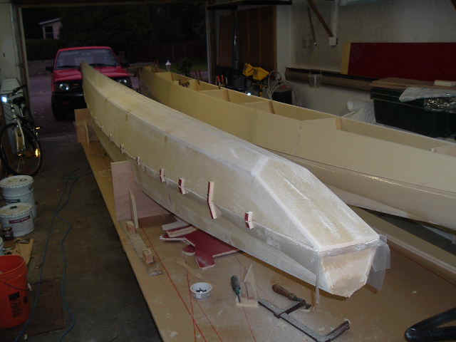
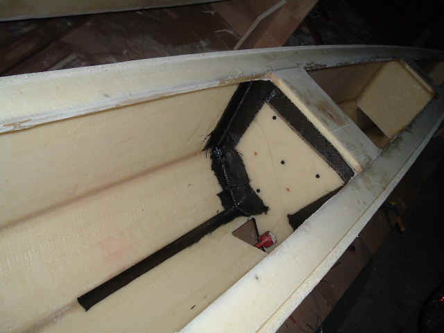
I used some carbon fiber around beam bulkheads to improve the stiffeness in
this critical area. I also added little "semi frames" to complete the
existing frames to eliminate the weakness caused by the square shape of
float frames. A frame failure would be a REAL pain to repair.
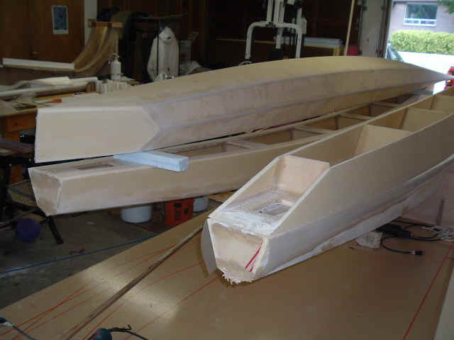
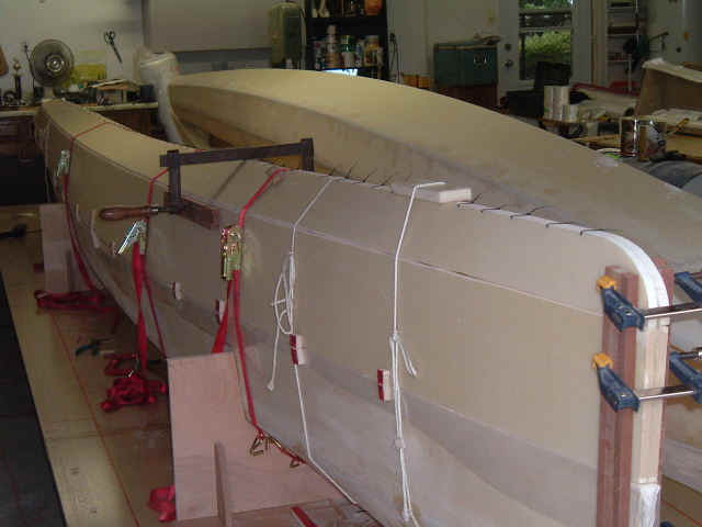
In the plans, Ray installs the cross beams after the floats are closed up.
By doing this it is impossible to laminate glass at the beam-float joint
inside the float, creating a weak area exactly where you want maximum
strength. I will instead fit the cross-beams BEFORE closing the floats.
This way access to the beam ends inside the float will be excellent. I will
again use carbon fiber there to make a 110% good structure that will not
flex or crack in the future.
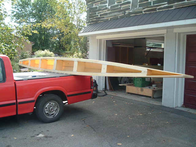
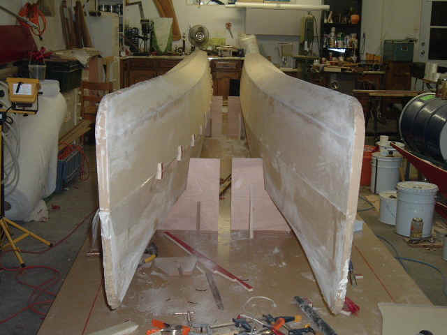
I changed the float transom shape. The plans asks to cut off the rear
section of assembled floats then glue on a flat transoms, taped only on the
outside. I changed that in order to be able to tape everything on the
inside as well, creating a stronger structure. Another benefit is the
possibility to keep the bottom portion of the floats complete (no cutting
off ). This is much less waistfull. It would break my heart to build nice
float ends only to cut them off and throw them in the garbage! With this
new shape it would be possible to update the full size panels to completely
eliminate any trimming required to install the transoms. Think about it
Ray! Warning: the new shape may be ugly to some...
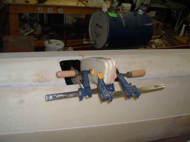
I changed the position of the shroud chainplate on the float. I moved it
from outside to inside, keeping the bolt holes at the same place. Since the
reinforcing glass and carbon is on the inside of the float, it makes more
sense to fit the stainless steel chainplates directly over it. Otherwise,
the bolts tend to bend from shroud loads and elongate the holes in the
float side panel, creating leaks. This way, the shear loads are transfered
directly to the reinforcing without any bolt bending. It also looks better
since only bolt heads with washers show on the float sides. Also, any
outboard loads will bend the chainplate away from the float side.The little
slot required on the float top will be reinforced by a little carbon plate
bonded from the top, holding the chainplate against any outboard loads.
Flexible sealant will be used around the chainplate (sikaflex or other).